Sales Hotline:
18970145687
Detailed description
[product introduction]
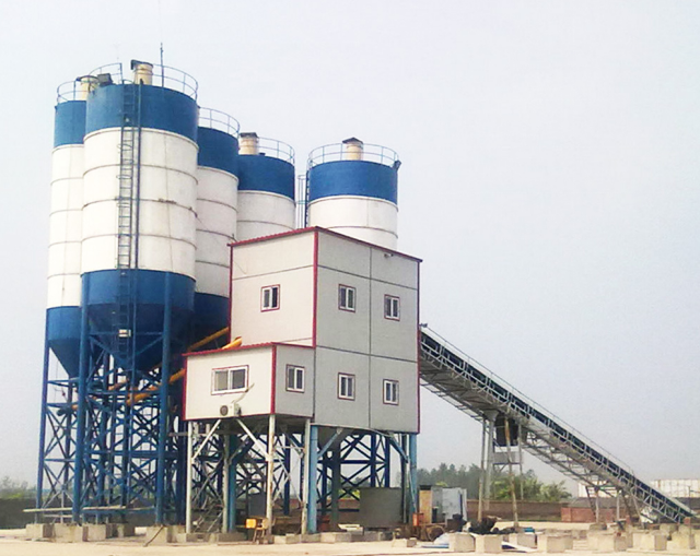
JS2000 concrete mixer discharging 2 cubic meters each time, also known as 2 cubic concrete mixer, 2 cubic mixer. The discharging cycle of JS2000 mixer is 60s. The main machine of 120 mixing station is the advanced and ideal construction equipment model at home and abroad, with high automation, good mixing quality, high efficiency, low energy consumption, low noise, convenient operation, fast unloading speed The lining plate and blade have the advantages of long service life, convenient maintenance, etc. It is suitable for mixing dry hard concrete, plastic concrete, mobile concrete, lightweight aggregate concrete and various mortars in all kinds of large, medium and small prefabricated component factories, highway, bridge, water conservancy, port, wharf and other industrial and civil construction departments.
In addition to being used as a single machine, it can also be combined with pld1600 batching unit into a simple mixing station, and can also be used as a supporting host of HZS50 mixing station. The machine has a series of advantages, such as even mixing, compact structure, beautiful appearance, stable operation, convenient operation, short cycle time, etc.
JS2000 double helix concrete mixer is composed of:
1. Mixing system: the mixing system is composed of motor, pulley, reducer, open gear, mixing device of mixing drum, oil supply device, etc. the motor is directly connected with cycloidal pin reducer, and the two output shafts of the reducer drive two horizontally configured mixing shafts to rotate in reverse and equal speed through two pairs of open gears. The arc part of the mixing drum is welded, and there are five kinds of lining plates embedded in the mixing drum, all of which are connected and fastened with the drum body with countersunk screws. The four observation covers on the mixing drum can be pushed out towards each other after being opened 90 °. A special sealing device is arranged at the joint of the mixing shaft and both ends of the mixing drum. In order to ensure the sealing quality, a special oil feeder is arranged on the end face of the mixing drum.
2. Feeding system: the feeding system is composed of winch mechanism, feeding gantry, hopper, feeding nozzle, etc. The brake motor drives the drum to rotate through the reducer, and the steel wire rope climbs up along the loading rack track through the pulley traction hopper. When it climbs to a certain height, a pair of rollers on the bucket door at the bottom of the hopper enter the water track of the loading rack, the bucket door opens automatically, and the materials are put into the mixing drum through the feeding nozzle. In order to ensure the hopper is in place accurately, a limit switch is installed on the feeding rack. There are two limit switches in the upper limit position, which are respectively used for raising limit and safety protection on the hopper. There is only one limit switch at the lower limit. When the hopper is lowered to the bottom of the pit, the steel wire rope is slightly loose. The strong spring lever mechanism makes the lower limit act and the winch mechanism stops automatically. The lower limit and spring lever mechanism are installed on the top of the upper guide rail. The upper part of the loading rack is foldable. It is connected with bolts and folded during transportation so as to reduce the transportation height. The brake motor can ensure that the hopper can stop at any position when it is in full load operation. The brake torque is adjusted by the large nut on the back of the motor.
3. Water supply system: the water supply system is composed of water pump, throttle valve, cleaning device and spray device. The flow of water can be regulated by the throttle valve driven by the cylinder, and the total amount of surface water supply is regulated by the electronic scale.
4. Unloading system: the unloading system is composed of unloading 6, air pump, reversing valve, air valve, air cylinder, electrical and other mechanisms. The unloading door is installed at the bottom of the mixer, and pneumatic unloading is realized through the air cylinder. And the opening and closing position of the discharge door. The sealing of the discharge door can be ensured by adjusting the position of the sealing strip. JS2000 unloading manual operating rod is used for emergency unloading in case of temporary power failure and cylinder failure. It should be removed at ordinary times to prevent personal injury.
5. Electrical system: the electrical control circuit is equipped with air switch, fuse and thermal relay, with short circuit protection and overload protection functions. All control buttons, air switch handles and indicator lights are arranged on the door of the distribution box, and are equipped with door locks. A protective cover is arranged outside the button. The electrical components in the distribution box are installed on an insulating board, which is safe, reliable and convenient for operation and maintenance. The electrical control power supply is 380V three-phase four wire power supply, and the allowable voltage error is ± 10%, otherwise, it is forbidden to use. If the power supply is provided by the user, the capacity shall be ≥ 100kVA. The surface temperature rise of the motor is ≤ 60 ℃, and the insulation of the live part to the shell is ≥ 0.5m Ω.
[technical parameters]

 TEL:
18079713117
Copyright © Ningdu xingye machinery manufacturing co. LTD Technical support:
Address:18079713117industrial park, ningdu county, ganzhou city, jiangxi province